Electronic Component Soldering
Carlos Amaro carlos.amaro@rice.edu
OEDK Engineering Design Technician
The sheer thought of soldering small electronic components may seem a bit frightening to some, however this may help you to avoid some common pitfalls. This guide is by no means “the bible” when it comes to soldering, however it will provide you with some helpful tips in soldering components. Some of you may have to solder circuit boards, wires, and or switches during a project and this will help to guide you.
Please bear in mind that soldering irons and guns get extremely hot and can burn fingers, wires, insulation, plastic and components. Keep in mind all lab safety rules and wear safety glasses when soldering. Also remember that solder contains lead so wash your hands when you are finished. Try to avoid breathing the smoke from soldering as well.
Determine the Job
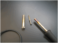
Look at what the scope of the job will be; will it be surface mount or thru hole, what type of wire is being used, am I making connectors or using switches? All of these things will have a direct effect on the soldering techniques that you use. The size of the components will determine the tip size for your soldering iron. Obviously you would not want to use the largest tip available for soldering a small capacitor, nor would you use the smallest tip to solder heavy gauge wire either. Be careful to choose the right size tip, because once the iron has been heated, it will take a while to cool off before the tip can be changed.
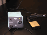
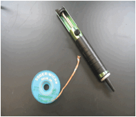
Soldering iron and various tips.
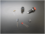
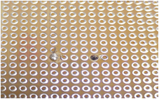
Different
electronic components.
Component
Preparation
Examine the component leads and foil runs on the board carefully and you will find that they probably need to be cleaned. Over time the leads can oxidize, but this can be removed with a pencil eraser. Just rub the eraser over the leads or foil runs and it will clean them off. You can also use isopropyl alcohol and a Q-tip to clean them as well, but the eraser trick works just as well. Be sure to clean off the eraser rubbings when done.
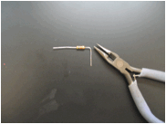
If your soldering involves using wires, then be sure to use the correct wire type and gauge. You may want to consider whether or not the wires need to be flexible or not. If yes, then you will need to use stranded wire. If you need to solder the wire to the board or to a connector, you should “tin” the tip of the wire first. Here’s how to do it: start by stripping back a bit of the insulation, not too much though. Apply a little bit of flux to the end of the wire that you want to “tin”. It is a resin that creates a quick heat transfer condition. Put a little bit of solder on the tip of the iron and then apply the tip to the wire in a gentle back and forth manner. If done correctly, the solder will flow from the iron and get sucked up into the wire strands to make them solid. This does not mean that the solder is so thick on the wire that it appears to be one solid mass. A good indicator of a well tinned wire is that you can still see the stranding of the wire through the solder. This will make the soldering of the stranded wire to a component, such as a switch, much easier to do. Be careful, if you hold the iron to the wire too long, you will cause the insulation to melt or the “tinning” to run up under the insulation; either one is not good. You can also get a good burn out of it too.
Tinning a wire is easily done.
Component Layout
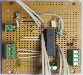
It has been my experience that it helps to lay out the components on the board before soldering anything in place. This will allow you to see how the components will physically look on the board. It will also let you to move things around before you make anything fixed. Keep in mind that your project board may have built in foil runs so make sure to utilize them effectively. I personally like to make power and ground rails so that they can be tapped from various points on the board.
Note how the components are arranged neatly.
You can use a pair of small needle nose pliers to make nice bends on component leads. This will help keep the circuit looking clean and neat. Make sure to position components carefully on you board. Try and keep the components equidistant from the solder junctions. Also remember that you can change the orientation of some components, like resistors, in order to save space.
Component lead formed with pliers.
Soldering Iron
Preparation
Once you have decided on the tip to use, install it on the soldering iron by unscrewing the retaining cover on the iron. Once the cover has been removed, gently pull the tip out of the end of the iron and replace it with the one you need to use. Re-install the retaining cover taking care not to cross thread the cover on the iron.
Soldering iron with retaining cover and tip removed.
Now that the iron has the correct tip installed, make sure the unit is turned off before you plug it in. Power up the unit and set the temperature control knob to about 600°F. You will need to wet (but don’t soak) the sponge that is provided with the unit. It will be used to help clean the tip of the iron.
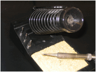
Note the wet sponge for iron cleaning.
Once the iron has reached temperature, you can clean the tip of the iron by gently wiping it on the sponge. Don’t leave it touching the sponge too long or it will burn and stick to the iron. You can repeat the process if the iron is still not clean, or try adding some solder to the tip and then try again. As long as there appears to be carbon coating the tip, it will not be clean and make soldering difficult if not impossible. DO NOT UNDER ANY CIRCUMSTANCES TRY TO USE AN ABRASIVE SUCH A SANDPAPER TO CLEAN THE TIP OF THE IRON. It will permanently damage the tip.
Now apply a bit of solder to the end of the iron and leave it there. This will act as a “bridge” to help transfer heat to the surfaces to be soldered.
Soldering…At Last
Now that the soldering iron and components are ready, you can solder them to your board. Start by placing your first component on the board in its proper location and orientation. If you are soldering components on a thru hole project board, you will need to be able to turn the boar over to solder the leads. You can use some tape to hold the component in place while the board is turned over. Don’t get a teammate to hold it while you solder since the component can get hot quickly and cause a nasty burn.
Don’t worry about trimming the excess lead length off for now; you can do it after the leads are soldered. One thing you can do to help solder components is use flux. You can apply it sparingly to the leads before you solder them to the board.
Use the iron to apply heat (sparingly) to the surfaces to be soldered. Try to heat them evenly so that the solder will bind to both at the same time. Remember to apply the solder to the component and not the iron, although you can get the solder to flow from the tip of the iron to the leads. Be sure to use the correct size of solder since it comes in a wide variety. You may have to adjust the temperature of you iron to help facilitate the process. Keep going and before you know it, all your components will be in place.
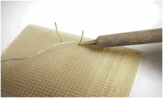
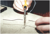
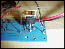
Soldering a thru-hole component
Soldering…The
Good, The Bad and The Ugly
So, how can you tell if your soldering job met any of the three above mentioned conditions? You can do this by examining your board/work carefully. See if you find any of the following conditions:
The Good:
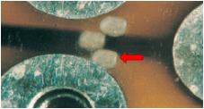
A good solder connection for a thru-hole component will have a shiny appearance and will have fillets from the surface of the board to the component leads. It will not have too much solder and have clean separation (no spikes of solder). The component leads will be neatly trimmed, near the surface of the board.
A good solder joint on the right, a bad one on the left.
The one on the left has too much solder.
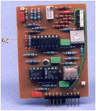
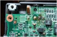
Good component placement is also a plus. Try to have the components flush with the surface of the board. The component leads are bent at a nice 90° and the components are not all right on top of each other. Any wires that have been added to the board are cut to length and soldered properly. Any stranded wire should have the leads “tinned”.
Note the nice clean wiring; components are neatly installed
and
flush mounted on the surface of the board.
The Bad:
The “cold” solder joint; this condition can be tricky. It will be dull in appearance and not have the usual nice, clean shiny surface. This can also be an indication of the lack of solder flow to one of the surfaces. Try to apply a little bit of heat to the junction to see if you can get them to flow together; maybe use some flux to help.
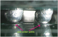
Hard to see, but they are defective; note how the
solder
does not make a good connection with the board.
“The bigger the glob, the better the job” is the only way to describe this condition. Do not have such an excess of solder that it looks like large silver blobs on your board. It can very easily lead to a shorting condition and burn up your circuitry. This can be remedied by using either a solder sucker, which is a manually operated vacuum pump or wicking which will “suck” up the solder. The wicking is trickier to use, but still effective. To use wicking, a copper mesh, you will need to pull a little bit out and then try to spread the strands apart at the end a bit. Then, place the wicking over the area where you want to remove the solder and apply the iron. The iron will heat the solder thru the wicking and the material will suck up the excess like a sponge or wick. If you are holding the wicking in place with your fingers, be careful because it transfers heat quite well and will get hot enough to burn you.

Good, but too much solder.
Use solder wick or the manual solder sucker to remedy.
The opposite condition of “the bigger the glob” is not enough solder. You should not have any gaps between the component leads and the board surface. Add a bit more solder, but avoid the previous mentioned condition.

The left lead of the 3-lead component lacks solder.
The Ugly:
Measling is a condition that occurs when the iron has been left on the PCB (printed circuit board) too long. The iron has heated the surface of the board so much that small white spots have appeared on the surface. This is an especially bad condition if you are utilizing a multilayered PCB. The excess heat can damage foil runs and connections on different layers of the board, which could render the board useless.
Note the white “spots” from too much heat.
Lifted pad or foil run- a condition similar to “measling”. What usually occurs is that the iron is used to heat a connection surface on the board, but it has gotten so hot that it has physically separated itself from the board. If this occurs, the best solution is to use a different pad or foil run since it can not be reattached to the board surface. Another alternative is to bypass the foil run with a jumper wire, however this can be difficult to achieve.
Burned component leads or a burned board connection- this is plainly obvious. The iron has been left in place too long or is too hot. Try to lower the iron temperature or try using a bit of flux to help solder quickly.
Note the burned appearance of the board.
This can be an indication of damaged components
because of overheating with the soldering iron.